ARN-2
Type
Personal Project
Year
2025
The following project is presents a computational validation study of an Axisymmetric Subsonic Jet (ASJ) issued from Acoustic Research Nozzle 2 (ARN2), utilizing the NASA Langley Turbulence Modeling Resource (TMR) database as a reference benchmark.
The purpose of this CFD simulation is to validate NASA's results by reproducing the aerodynamic and turbulence characteristics of the ARN2. Specifically, this study aims to evaluate the accuracy of the numerical setup focusing on mesh independence and the performance of the Spalart Allmaras turbulence model in capturing the complex flow physics of an axisymmetric subsonic jet. By comparing computational data directly against the validated empirical profiles provided by the NASA TMR, we result on a conclusion that the Spalart Allmaras model is not reliable in predicting unconfined free shear flows. The model offers great advantages like excellent computational efficiency being a simple one equation model and high accuracy for wall bounded flows inside the nozzle. To consider further steps for better results, Switching to a high fidelity model like k omega SST to accurately capture downstream plume development.
For further informations download the support of the case study below.


Geometry Development
Geometry Development
Geometry Development
The geometric fidelity of ARN2 serves as the critical baseline for numerical validation. The internal and external lip profiles were accurately reconstructed and simplfied in SOLIDWORKS using the official coordinates (x, y) supplied by the NASA Langley Turbulence Modeling Resource database, as shown in both pictures.
The geometric fidelity of ARN2 serves as the critical baseline for numerical validation. The internal and external lip profiles were accurately reconstructed and simplfied in SOLIDWORKS using the official coordinates (x, y) supplied by the NASA Langley Turbulence Modeling Resource database, as shown in both pictures.
The internal convergent profile follows a cubic polynomial curve defined over the axial interval from X = 0 to 6.825 inches.
The internal convergent profile follows a cubic polynomial curve defined over the axial interval from X = 0 to 6.825 inches.
Using this governing equation, a 2D simplified axisymmetric geometry of the nozzle exhaust was generated to later construct the surrounding computational domain in ANSYS.
Using this governing equation, a 2D simplified axisymmetric geometry of the nozzle exhaust was generated to later construct the surrounding computational domain in ANSYS.
To balance numerical accuracy with computational efficiency, geometric features were selectively simplified. Essential inner and outer nozzle curvatures critical to flow physics were retained, while non-critical external features with negligible impact on the far-field flow development were omitted to optimize meshing and reduce calculation time.
To balance numerical accuracy with computational efficiency, geometric features were selectively simplified. Essential inner and outer nozzle curvatures critical to flow physics were retained, while non-critical external features with negligible impact on the far-field flow development were omitted to optimize meshing and reduce calculation time.


Computational Domain Dimentions
Computational Domain Dimentions
Computational Domain Dimentions
Given the geometric and physical axisymmetry of the nozzle and its subsequent exhaust plume, the 3D physical domain was modeled using a 2D axisymmetric formulation. This reduction significantly decreases CPU runtime while enabling high grid resolution in critical, high-gradient regions.
The computational domain encompasses both the internal nozzle fluid volume and a large external free-stream boundaries dimensioned according to NASA TMR guidelines relative to the exit diameter Djet:
Given the geometric and physical axisymmetry of the nozzle and its subsequent exhaust plume, the 3D physical domain was modeled using a 2D axisymmetric formulation. This reduction significantly decreases CPU runtime while enabling high grid resolution in critical, high-gradient regions.
The computational domain encompasses both the internal nozzle fluid volume and a large external free-stream boundaries dimensioned according to NASA TMR guidelines relative to the exit diameter Djet:
• Downstream Extent (Axial): The domain extends to x = 60Djet from the exit plane to fully capture the potential core development, transition zone, and downstream jet decay.
• Radial Extent: The upper atmospheric far-field boundary is positioned at y = 30Djet relative to the centerline, ensuring unhindered ambient air entrainment without boundary-induced constraints.
• Downstream Extent (Axial): The domain extends to x = 60Djet from the exit plane to fully capture the potential core development, transition zone, and downstream jet decay.
• Radial Extent: The upper atmospheric far-field boundary is positioned at y = 30Djet relative to the centerline, ensuring unhindered ambient air entrainment without boundary-induced constraints.
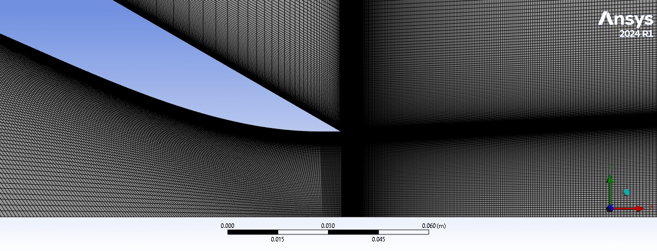
To maintain structured grid control, the domain was partitioned into 7 distinct sub-zones, each tailored with specific cell distributions and growth rates. Interface topology across region boundaries was configured to ensure smooth cell sizing transitions, eliminating severe grid jump discontinuities that could introduce numerical diffusion or convergence instability.
To maintain structured grid control, the domain was partitioned into 7 distinct sub-zones, each tailored with specific cell distributions and growth rates. Interface topology across region boundaries was configured to ensure smooth cell sizing transitions, eliminating severe grid jump discontinuities that could introduce numerical diffusion or convergence instability.
Boundary Conditions
Boundary Conditions
Boundary Conditions
The boundary conditions are strictly calibrated following the NASA Langley Turbulence Modeling Resource specifications to yield a target jet exit Mach number of Mjet = 0.51
The boundary conditions are strictly calibrated following the NASA Langley Turbulence Modeling Resource specifications to yield a target jet exit Mach number of Mjet = 0.51
• Pressure Inlet: the gauge pressure is pg = 19931.6407 Pa and the Stagnation temperature T0 is maintained at 300 K.
•Freestream(pressure far field): To match the NASA TMR benchmark where the freestream static pressure ratio is uniform ( p/p∞= 1.0), a negligible co-flowing background velocity of Mref = 0.01 is implemented, with a turbulence viscosity ratio of 5 (the ratio between the laminar viscosity to theturbulence viscosity)
• Outer and Far-Field Outflow (Pressure Outlet): the gauge pressure specified at the outlets is set to 0 Pa.
No-Slip Wall condition : set for both internal and external solid geometric boundaries
• Pressure Inlet: the gauge pressure is pg = 19931.6407 Pa and the Stagnation temperature T0 is maintained at 300 K.
•Freestream(pressure far field): To match the NASA TMR benchmark where the freestream static pressure ratio is uniform ( p/p∞= 1.0), a negligible co-flowing background velocity of Mref = 0.01 is implemented, with a turbulence viscosity ratio of 5 (the ratio between the laminar viscosity to theturbulence viscosity)
• Outer and Far-Field Outflow (Pressure Outlet): the gauge pressure specified at the outlets is set to 0 Pa.
No-Slip Wall condition : set for both internal and external solid geometric boundaries
The steady compressible Navier-Stokes equations are resolved using the density based solver with an implicit formulation in ANSYS Fluent, using Second-Order Upwind, minimizing numerical diffusion in the free shear mixing layer. For the Modified Turbulent Viscosity we use First-Order Upwind, ensuring high numerical stability for the Spalart-Allmaras model.
The steady compressible Navier-Stokes equations are resolved using the density based solver with an implicit formulation in ANSYS Fluent, using Second-Order Upwind, minimizing numerical diffusion in the free shear mixing layer. For the Modified Turbulent Viscosity we use First-Order Upwind, ensuring high numerical stability for the Spalart-Allmaras model.

Convergence Criteria and Residual Monitoring
Convergence Criteria and Residual Monitoring
To verify steady-state convergence and ensure the solution is free from numerical oscillations, the tracking of normalized residuals was conducted over 4000 iterations
To verify steady-state convergence and ensure the solution is free from numerical oscillations, the tracking of normalized residuals was conducted over 4000 iterations
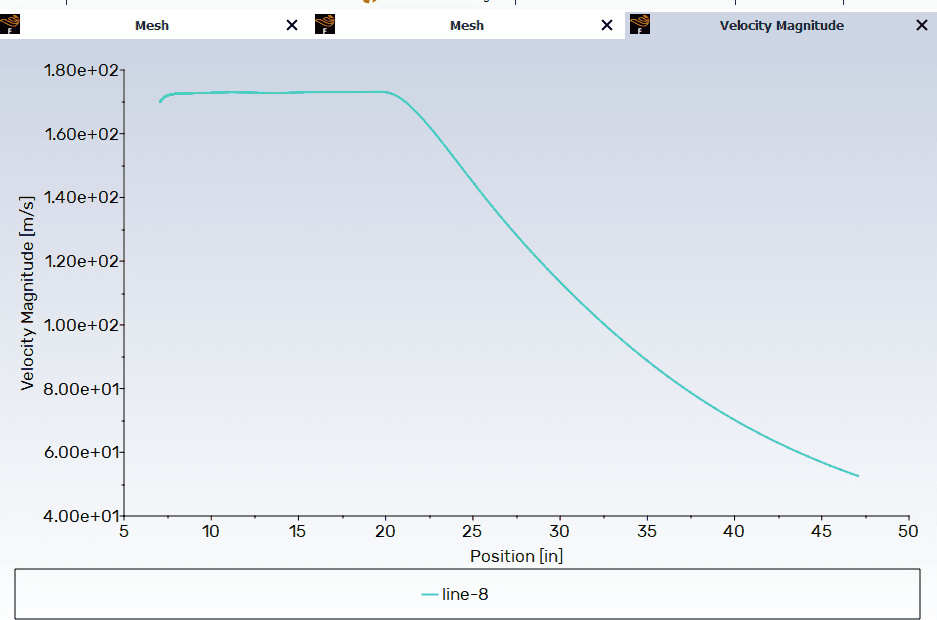
To quantitatively analyze jet decay and potential core degradation, the velocity magnitude was extracted long the nozzle’s central axis of symmetry (y = 0) spanning an axial distribution from the entry down to an exhaust position of x = 47 inches
To quantitatively analyze jet decay and potential core degradation, the velocity magnitude was extracted long the nozzle’s central axis of symmetry (y = 0) spanning an axial distribution from the entry down to an exhaust position of x = 47 inches
As presented in the right figure, the flow velocity registers a steep acceleration within the internal nozzle channel, climbing rapidly from an initial entry value to its peak operating velocity of approximately 173 m/s. This peak velocity forms a stable plateau between x = 7 inches and x = 20 inches, defining the exact physical boundaries of the non-degraded potential core of the jet plume. Beyond x = 20 inches, the potential core undergoes significant momentum shear interaction with the surrounding environment, initiating a smooth, continuous exponential decay that drops to nearly 53 m/s at the far downstream boundary limit.
As presented in the right figure, the flow velocity registers a steep acceleration within the internal nozzle channel, climbing rapidly from an initial entry value to its peak operating velocity of approximately 173 m/s. This peak velocity forms a stable plateau between x = 7 inches and x = 20 inches, defining the exact physical boundaries of the non-degraded potential core of the jet plume. Beyond x = 20 inches, the potential core undergoes significant momentum shear interaction with the surrounding environment, initiating a smooth, continuous exponential decay that drops to nearly 53 m/s at the far downstream boundary limit.

Results, Discussion, and Validation
Results, Discussion, and Validation
As illustrated in Velocity contour figure, the fluid accelerates rapidly through the internal convergent profile of the nozzle, reaching its peak velocity profile directly at the exit plane (x/Djet = 0). The potential core of the jet remains highly distinct and preserved downstream along the axis of symmetry, extending to approximately x = 5Djet to 6Djet before turning into the fully developed jet decay region.
As illustrated in Velocity contour figure, the fluid accelerates rapidly through the internal convergent profile of the nozzle, reaching its peak velocity profile directly at the exit plane (x/Djet = 0). The potential core of the jet remains highly distinct and preserved downstream along the axis of symmetry, extending to approximately x = 5Djet to 6Djet before turning into the fully developed jet decay region.
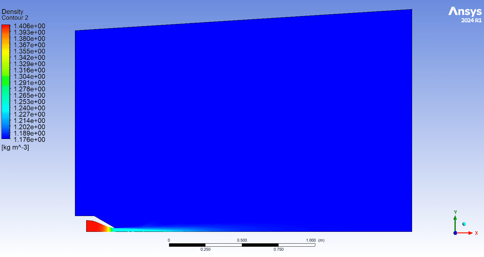
The density field displayed in the next image confirms the compressible nature of the subsonic flow setup. High stagnation density values are concentrated within the internal nozzle domain up to the throat zone, showing a smooth expansion as the fluid shears into the lower-density ambient atmospher.
The density field displayed in the next image confirms the compressible nature of the subsonic flow setup. High stagnation density values are concentrated within the internal nozzle domain up to the throat zone, showing a smooth expansion as the fluid shears into the lower-density ambient atmospher.



The final results show good agreement with the benchmark data provided by the NASA TMR. However, the Spalart-Allmaras turbulence model exhibited convergence difficulties, requiring several iteration attempts and solver tuning to achieve stable numerical convergence. To address this limitation, future work will incorporate the K-omega-SST model to evaluate its stability and systematically compare the predictive accuracy of both turbulence models.
The final results show good agreement with the benchmark data provided by the NASA TMR. However, the Spalart-Allmaras turbulence model exhibited convergence difficulties, requiring several iteration attempts and solver tuning to achieve stable numerical convergence. To address this limitation, future work will incorporate the K-omega-SST model to evaluate its stability and systematically compare the predictive accuracy of both turbulence models.
More Projects
More Projects

Geometry Development
The geometric fidelity of ARN2 serves as the critical baseline for numerical validation. The internal and external lip profiles were accurately reconstructed and simplfied in SOLIDWORKS using the official coordinates (x, y) supplied by the NASA Langley Turbulence Modeling Resource database, as shown in both pictures.
The internal convergent profile follows a cubic polynomial curve defined over the axial interval from X = 0 to 6.825 inches.
Using this governing equation, a 2D simplified axisymmetric geometry of the nozzle exhaust was generated to later construct the surrounding computational domain in ANSYS.
To balance numerical accuracy with computational efficiency, geometric features were selectively simplified. Essential inner and outer nozzle curvatures critical to flow physics were retained, while non-critical external features with negligible impact on the far-field flow development were omitted to optimize meshing and reduce calculation time.
Computational Domain Dimentions
Given the geometric and physical axisymmetry of the nozzle and its subsequent exhaust plume, the 3D physical domain was modeled using a 2D axisymmetric formulation. This reduction significantly decreases CPU runtime while enabling high grid resolution in critical, high-gradient regions.
The computational domain encompasses both the internal nozzle fluid volume and a large external free-stream boundaries dimensioned according to NASA TMR guidelines relative to the exit diameter Djet:
• Downstream Extent (Axial): The domain extends to x = 60Djet from the exit plane to fully capture the potential core development, transition zone, and downstream jet decay.
• Radial Extent: The upper atmospheric far-field boundary is positioned at y = 30Djet relative to the centerline, ensuring unhindered ambient air entrainment without boundary-induced constraints.
To maintain structured grid control, the domain was partitioned into 7 distinct sub-zones, each tailored with specific cell distributions and growth rates. Interface topology across region boundaries was configured to ensure smooth cell sizing transitions, eliminating severe grid jump discontinuities that could introduce numerical diffusion or convergence instability.
Boundary Conditions
The boundary conditions are strictly calibrated following the NASA Langley Turbulence Modeling Resource specifications to yield a target jet exit Mach number of Mjet = 0.51
• Pressure Inlet: the gauge pressure is pg = 19931.6407 Pa and the Stagnation temperature T0 is maintained at 300 K.
•Freestream(pressure far field): To match the NASA TMR benchmark where the freestream static pressure ratio is uniform ( p/p∞= 1.0), a negligible co-flowing background velocity of Mref = 0.01 is implemented, with a turbulence viscosity ratio of 5 (the ratio between the laminar viscosity to theturbulence viscosity)
• Outer and Far-Field Outflow (Pressure Outlet): the gauge pressure specified at the outlets is set to 0 Pa.
No-Slip Wall condition : set for both internal and external solid geometric boundaries
The steady compressible Navier-Stokes equations are resolved using the density based solver with an implicit formulation in ANSYS Fluent, using Second-Order Upwind, minimizing numerical diffusion in the free shear mixing layer. For the Modified Turbulent Viscosity we use First-Order Upwind, ensuring high numerical stability for the Spalart-Allmaras model.
Convergence Criteria and Residual Monitoring
To verify steady-state convergence and ensure the solution is free from numerical oscillations, the tracking of normalized residuals was conducted over 4000 iterations
To quantitatively analyze jet decay and potential core degradation, the velocity magnitude was extracted long the nozzle’s central axis of symmetry (y = 0) spanning an axial distribution from the entry down to an exhaust position of x = 47 inches
As presented in the right figure, the flow velocity registers a steep acceleration within the internal nozzle channel, climbing rapidly from an initial entry value to its peak operating velocity of approximately 173 m/s. This peak velocity forms a stable plateau between x = 7 inches and x = 20 inches, defining the exact physical boundaries of the non-degraded potential core of the jet plume. Beyond x = 20 inches, the potential core undergoes significant momentum shear interaction with the surrounding environment, initiating a smooth, continuous exponential decay that drops to nearly 53 m/s at the far downstream boundary limit.
Results, Discussion, and Validation
As illustrated in Velocity contour figure, the fluid accelerates rapidly through the internal convergent profile of the nozzle, reaching its peak velocity profile directly at the exit plane (x/Djet = 0). The potential core of the jet remains highly distinct and preserved downstream along the axis of symmetry, extending to approximately x = 5Djet to 6Djet before turning into the fully developed jet decay region.
The density field displayed in the next image confirms the compressible nature of the subsonic flow setup. High stagnation density values are concentrated within the internal nozzle domain up to the throat zone, showing a smooth expansion as the fluid shears into the lower-density ambient atmospher.
The final results show good agreement with the benchmark data provided by the NASA TMR. However, the Spalart-Allmaras turbulence model exhibited convergence difficulties, requiring several iteration attempts and solver tuning to achieve stable numerical convergence. To address this limitation, future work will incorporate the K-omega-SST model to evaluate its stability and systematically compare the predictive accuracy of both turbulence models.