Rocketry Competition
Type
Team project
Year
2026
TEKNOFEST COMPETITION is a well-known competition that gathers students from around the world to compete in different fields in Turkey. We applied for the Rocketry Competition and started working on it for months, passing from the Priliminary Design to the Critical Design.
Throughout the project, I have been responsible under the Team Leader's guidance. We started by reading the instruction book, identifying the purpose of the deployment, and understanding how the final design should be. We started by using OpenRocket, which is a simulation software made for rockets, inserting all the components of the rocket, from the nose cone, body tubes, coupler, fins, motor, parachutes… and adding their weight by either calculating it in SolidWorks, adding the drag coefficient of the parachutes, material of the shock cords, and other components to ensure that the design is highly accurate.
The 3D modeling of the motor, the entire rocket, and the attention to the smallest details were really important. Even the smallest NUT was counted in the process, in order to calculate the weight of the final rocket and the payload required for the competition. And, of course, the CFD simulation and structural analysis were required for this project.
After that, we moved to the manufacturing process, where we started building the rocket body using fiberglass and resin. After ensuring that the mixture of the resin and accelerator was correct, we started building the body, along with rectangular sheets for the tests, to document the results of the combination of the different layers of fiberglass.
The following context contains more details about my work with my teammates.
TEKNOFEST COMPETITION is a well-known competition that gathers students from around the world to compete in different fields in Turkey. We applied for the Rocketry Competition and started working on it for months, passing from the Priliminary Design to the Critical Design.
Throughout the project, I have been responsible under the Team Leader's guidance. We started by reading the instruction book, identifying the purpose of the deployment, and understanding how the final design should be. We started by using OpenRocket, which is a simulation software made for rockets, inserting all the components of the rocket, from the nose cone, body tubes, coupler, fins, motor, parachutes… and adding their weight by either calculating it in SolidWorks, adding the drag coefficient of the parachutes, material of the shock cords, and other components to ensure that the design is highly accurate.
The 3D modeling of the motor, the entire rocket, and the attention to the smallest details were really important. Even the smallest NUT was counted in the process, in order to calculate the weight of the final rocket and the payload required for the competition. And, of course, the CFD simulation and structural analysis were required for this project.
After that, we moved to the manufacturing process, where we started building the rocket body using fiberglass and resin. After ensuring that the mixture of the resin and accelerator was correct, we started building the body, along with rectangular sheets for the tests, to document the results of the combination of the different layers of fiberglass.
The following context contains more details about my work with my teammates.

OpenRocket Design
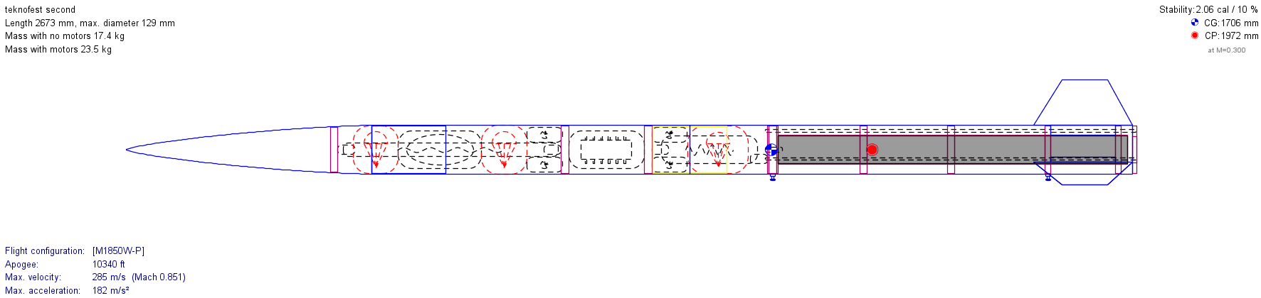
Working under the competition's specifications was both challenging and exciting. While designing in OpenRocket, I had to keep in mind the motor parameters and specifications such as its dimensions and thrust profile. Although the total rocket length was not strictly fixed, the stability margin was constrained to remain under 2.5 cal. Based on this criteria, we established the design: two separate body tubes joined by a coupler, an ogive nose cone with a length to diameter ratio of 5:1, and clipped delta (trapezoidal) fins.
The internal recovery and electronic systems include three parachutes (main, drogue, and payload), an avionics system with 4 Black Powder, and shock cords. The sizing of each component was carefully sized and validated against previous rocket data.
Working under the competition's specifications was both challenging and exciting. While designing in OpenRocket, I had to keep in mind the motor parameters and specifications such as its dimensions and thrust profile. Although the total rocket length was not strictly fixed, the stability margin was constrained to remain under 2.5 cal. Based on this criteria, we established the design: two separate body tubes joined by a coupler, an ogive nose cone with a length to diameter ratio of 5:1, and clipped delta (trapezoidal) fins.
The internal recovery and electronic systems include three parachutes (main, drogue, and payload), an avionics system with 4 Black Powder, and shock cords. The sizing of each component was carefully sized and validated against previous rocket data.
SolidWorks Design
In the following sections i will show the different parts of the Rocket, the following assembly contains the essential parts in the rocket
In the following sections i will show the different parts of the Rocket, the following assembly contains the essential parts in the rocket

To make sure the Design is accurate for future calculations such as the CG, and the weight of components, modeling the solid rocket motor with exact physical specifications was essential, by reverse engineering it directly from competition specification drawings, I tried to build it as accurate as possible putting in mind the conversion of units from inch to cm as illustrated in the following images.
To make sure the Design is accurate for future calculations such as the CG, and the weight of components, modeling the solid rocket motor with exact physical specifications was essential, by reverse engineering it directly from competition specification drawings, I tried to build it as accurate as possible putting in mind the conversion of units from inch to cm as illustrated in the following images.


Accurate CAD modeling of the nozzle geometry was critical for engineering the lower motor retaining ring, which is essential to maintaining structural integrity under static ground handling, launch acceleration, and the reverse inertial forces experienced at apogee during recovery deployment. Additionally, thermal expansion of the nozzle during burn was taken into account when designing the motor retainer and its contact interface, ensuring the shoulder properly supports the entire motor casing.
The following pictures showcase the Nozzle, the Motor retainer and the assembly illustrate the shoulder part.
Accurate CAD modeling of the nozzle geometry was critical for engineering the lower motor retaining ring, which is essential to maintaining structural integrity under static ground handling, launch acceleration, and the reverse inertial forces experienced at apogee during recovery deployment. Additionally, thermal expansion of the nozzle during burn was taken into account when designing the motor retainer and its contact interface, ensuring the shoulder properly supports the entire motor casing.
The following pictures showcase the Nozzle, the Motor retainer and the assembly illustrate the shoulder part.

Nozzle Technical drawing
Nozzle Technical drawing

Nozzle sketch
Nozzle sketch

Motor retainer
Motor retainer

Assembly- contact between Motor retainer and Motor casting
Assembly- contact between Motor retainer and Motor casting
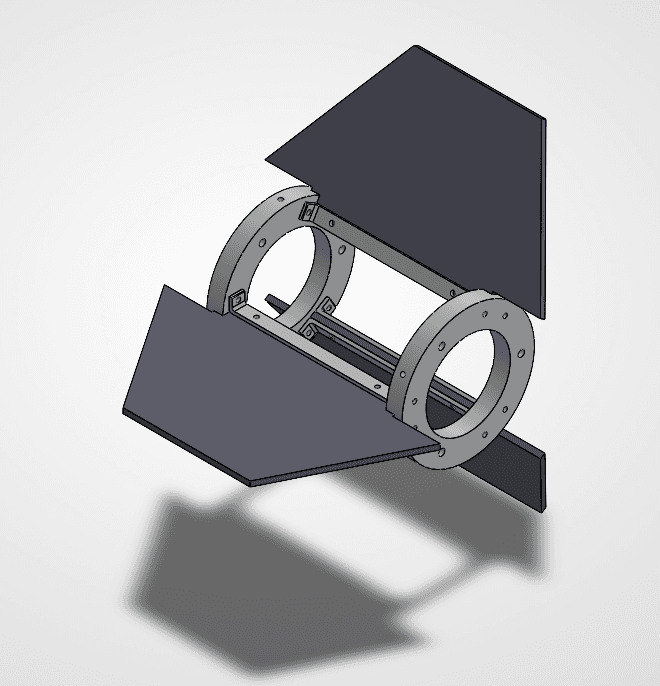
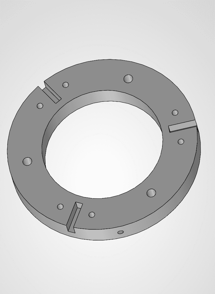
Based on OpenRocket aerodynamic simulation data, a modular support structure was engineered to lock all three fins rigidly in place against high aerodynamic loads. Each fin is sandwiched between dual retention plates and fastened with bolts. Customized centering rings feature 3 mm precision keyway slots to index fin alignment, and then the 2 plates were fastened with bolts in both sides with the centering rings. To prevent axial rotation during flight, three alignment threaded rods pass longitudinally through the assembly, after inserting the whole assembly in the Rocket, 3 radial set screws thread through the centering rings to lock the complete fin canister to the main body tube.
Based on OpenRocket aerodynamic simulation data, a modular support structure was engineered to lock all three fins rigidly in place against high aerodynamic loads. Each fin is sandwiched between dual retention plates and fastened with bolts. Customized centering rings feature 3 mm precision keyway slots to index fin alignment, and then the 2 plates were fastened with bolts in both sides with the centering rings. To prevent axial rotation during flight, three alignment threaded rods pass longitudinally through the assembly, after inserting the whole assembly in the Rocket, 3 radial set screws thread through the centering rings to lock the complete fin canister to the main body tube.
Fins support Assembly
Fins support Assembly
Centering Ring
Centering Ring
CFD Simulation
I run a CFD simulation on a the rocket by useing the results from OpenRocket as inputs, also i put in consideration the rail buttons as required in the competition specifications.
I run a CFD simulation on a the rocket by useing the results from OpenRocket as inputs, also i put in consideration the rail buttons as required in the competition specifications.


Velocity countour


Pressure countour
The Tube & Nose Cone Fabrication
For the rocket body, and nose cone, we utilized fiberglass composite construction. A 125 mm PVC pipe rated at PN10 (nominal pressure) served as the inner mandrel. We specifically selected PN10 over lower-rated PN6 pipe because the exothermic chemical reaction of the curing resin generates significant heat; a thinner PN6 pipe would warp or deform under these thermal stresses, ruining the mold geometry.
For the nose cone, a 3D-printed female mold was fabricated to ensure precise aerodynamic contours.
To facilitate mold release, the mandrel pipe was thoroughly sanded and lubricated with grease (or high grade Vaseline), followed by a protective layer of parchment paper (papier cuisson). This release stack ensures easy extraction of the composite tube after curing. The layup schedule was empirically tested and optimized to achieve a structural wall thickness of 2 mm. During the resin application, the tube must be continuously rotated to distribute the resin evenly; post-layup rotation is equally critical throughout the initial curing phase to prevent resin pooling and sagging.
For the rocket body, and nose cone, we utilized fiberglass composite construction. A 125 mm PVC pipe rated at PN10 (nominal pressure) served as the inner mandrel. We specifically selected PN10 over lower-rated PN6 pipe because the exothermic chemical reaction of the curing resin generates significant heat; a thinner PN6 pipe would warp or deform under these thermal stresses, ruining the mold geometry.
For the nose cone, a 3D-printed female mold was fabricated to ensure precise aerodynamic contours.
To facilitate mold release, the mandrel pipe was thoroughly sanded and lubricated with grease (or high grade Vaseline), followed by a protective layer of parchment paper (papier cuisson). This release stack ensures easy extraction of the composite tube after curing. The layup schedule was empirically tested and optimized to achieve a structural wall thickness of 2 mm. During the resin application, the tube must be continuously rotated to distribute the resin evenly; post-layup rotation is equally critical throughout the initial curing phase to prevent resin pooling and sagging.


The Fins
The Fins
The Fins
The fins will be manufactured using a different method than the body tube. The body tube wall thickness is designed to be 2 mm, whereas the fins require a 5 mm thickness to withstand external aerodynamic forces. Because of this, we fabricated four identical pieces simultaneously. As my previous team leader, Taha Chaanoun, advised: "Identical fins built simultaneously are always better than perfect ones built separately." Taking his advice, we used a tested lay-up technique layering triaxial fabric, mat, and finishing fiberglass (triaxial, mat, finition) to produce four fins—three for the rocket assembly and one dedicated to structural testing for the video documentation.
After applying all the layers, we cut between the 4 parts while keeping margin for the lazer cutter. We used a manual cutter at this stage because the laser cutter bed was not large enough to accommodate all four combined fins at once.
To optimize the compression process without a vacuum pump (pompe sous vide), we used a alternative technique: we stacked all four wet lay-up pieces on top of each other, separating each layer with parchment paper (papier cuisson), and applied heavy weights on top. This compression method successfully squeezed out excess resin and purged trapped air bubbles.
Finally, for precise final shaping of the cured fin profiles, using a CNC or CO2 laser cutter is far superior to cutting them manually with a saw, as manual sawing damages the fiberglass edges and compromises the final geometry.
The fins will be manufactured using a different method than the body tube. The body tube wall thickness is designed to be 2 mm, whereas the fins require a 5 mm thickness to withstand external aerodynamic forces. Because of this, we fabricated four identical pieces simultaneously. As my previous team leader, Taha Chaanoun, advised: "Identical fins built simultaneously are always better than perfect ones built separately." Taking his advice, we used a tested lay-up technique layering triaxial fabric, mat, and finishing fiberglass (triaxial, mat, finition) to produce four fins—three for the rocket assembly and one dedicated to structural testing for the video documentation.
After applying all the layers, we cut between the 4 parts while keeping margin for the lazer cutter. We used a manual cutter at this stage because the laser cutter bed was not large enough to accommodate all four combined fins at once.
To optimize the compression process without a vacuum pump (pompe sous vide), we used a alternative technique: we stacked all four wet lay-up pieces on top of each other, separating each layer with parchment paper (papier cuisson), and applied heavy weights on top. This compression method successfully squeezed out excess resin and purged trapped air bubbles.
Finally, for precise final shaping of the cured fin profiles, using a CNC or CO2 laser cutter is far superior to cutting them manually with a saw, as manual sawing damages the fiberglass edges and compromises the final geometry.


More Projects
More Projects

OpenRocket Design
Working under the competition's specifications was both challenging and exciting. While designing in OpenRocket, I had to keep in mind the motor parameters and specifications such as its dimensions and thrust profile. Although the total rocket length was not strictly fixed, the stability margin was constrained to remain under 2.5 cal. Based on this criteria, we established the design: two separate body tubes joined by a coupler, an ogive nose cone with a length to diameter ratio of 5:1, and clipped delta (trapezoidal) fins.
The internal recovery and electronic systems include three parachutes (main, drogue, and payload), an avionics system with 4 Black Powder, and shock cords. The sizing of each component was carefully sized and validated against previous rocket data.
SolidWorks Design
In the following sections i will show the different parts of the Rocket, the following assembly contains the essential parts in the rocket
To make sure the Design is accurate for future calculations such as the CG, and the weight of components, modeling the solid rocket motor with exact physical specifications was essential, by reverse engineering it directly from competition specification drawings, I tried to build it as accurate as possible putting in mind the conversion of units from inch to cm as illustrated in the following images.
Accurate CAD modeling of the nozzle geometry was critical for engineering the lower motor retaining ring, which is essential to maintaining structural integrity under static ground handling, launch acceleration, and the reverse inertial forces experienced at apogee during recovery deployment. Additionally, thermal expansion of the nozzle during burn was taken into account when designing the motor retainer and its contact interface, ensuring the shoulder properly supports the entire motor casing.
The following pictures showcase the Nozzle, the Motor retainer and the assembly illustrate the shoulder part.
Nozzle Technical drawing
Nozzle sketch
Motor retainer
Assembly- contact between Motor retainer and Motor casting
Based on OpenRocket aerodynamic simulation data, a modular support structure was engineered to lock all three fins rigidly in place against high aerodynamic loads. Each fin is sandwiched between dual retention plates and fastened with bolts. Customized centering rings feature 3 mm precision keyway slots to index fin alignment, and then the 2 plates were fastened with bolts in both sides with the centering rings. To prevent axial rotation during flight, three alignment threaded rods pass longitudinally through the assembly, after inserting the whole assembly in the Rocket, 3 radial set screws thread through the centering rings to lock the complete fin canister to the main body tube.
Fins support Assembly
Centering Ring
CFD Simulation
I run a CFD simulation on a the rocket by useing the results from OpenRocket as inputs, also i put in consideration the rail buttons as required in the competition specifications.
Velocity countour
Pressure countour
The Tube & Nose Cone Fabrication
For the rocket body, and nose cone, we utilized fiberglass composite construction. A 125 mm PVC pipe rated at PN10 (nominal pressure) served as the inner mandrel. We specifically selected PN10 over lower-rated PN6 pipe because the exothermic chemical reaction of the curing resin generates significant heat; a thinner PN6 pipe would warp or deform under these thermal stresses, ruining the mold geometry.
For the nose cone, a 3D-printed female mold was fabricated to ensure precise aerodynamic contours.
To facilitate mold release, the mandrel pipe was thoroughly sanded and lubricated with grease (or high grade Vaseline), followed by a protective layer of parchment paper (papier cuisson). This release stack ensures easy extraction of the composite tube after curing. The layup schedule was empirically tested and optimized to achieve a structural wall thickness of 2 mm. During the resin application, the tube must be continuously rotated to distribute the resin evenly; post-layup rotation is equally critical throughout the initial curing phase to prevent resin pooling and sagging.
The Fins
The fins will be manufactured using a different method than the body tube. The body tube wall thickness is designed to be 2 mm, whereas the fins require a 5 mm thickness to withstand external aerodynamic forces. Because of this, we fabricated four identical pieces simultaneously. As my previous team leader, Taha Chaanoun, advised: "Identical fins built simultaneously are always better than perfect ones built separately." Taking his advice, we used a tested lay-up technique layering triaxial fabric, mat, and finishing fiberglass (triaxial, mat, finition) to produce four fins—three for the rocket assembly and one dedicated to structural testing for the video documentation.
After applying all the layers, we cut between the 4 parts while keeping margin for the lazer cutter. We used a manual cutter at this stage because the laser cutter bed was not large enough to accommodate all four combined fins at once.
To optimize the compression process without a vacuum pump (pompe sous vide), we used a alternative technique: we stacked all four wet lay-up pieces on top of each other, separating each layer with parchment paper (papier cuisson), and applied heavy weights on top. This compression method successfully squeezed out excess resin and purged trapped air bubbles.
Finally, for precise final shaping of the cured fin profiles, using a CNC or CO2 laser cutter is far superior to cutting them manually with a saw, as manual sawing damages the fiberglass edges and compromises the final geometry.